A few weeks ago, I lashed out and purchased a Samsung SHS-1321 digital door lock from eBay. It’s a very stylish unit with nice capacitive touch buttons and an RFID card reader for keyless entry.
Product information: http://www.samsungdigitallife.com/SHS-1320.php
For $143, this lock does an amazing job. It can be programmed with up to 20 different access cards, which is more that enough for most home users i.e. the target market. That said, there are some shortcomings-
Programming a new card erases the existing cards
The instruction say otherwise, but this is what seems to be happening to me. Effectively this means that I’d have to ensure I have all cards/tags present when programming up a new one.
You cannot remove a specific card
This seems fairly self evident considering the lock is a standalone system with no management interface. If you were to lose a card/tag, you need to erase all cards and start again.
No record keeping ability
Again, as a cheap standalone product, there is no logging available. Given each access card is unique, this would be a nice feature.
Only the card UID is used
Ok this one depends on how paranoid you want to be, but it is worth knowing. ISO1443 RFID cards have a unique identifier which can be read with any compatible reader – i.e. it is not meant to be secure. The Samsung lock (and probably others) read this UID and use that as the only means to identify access cards – i.e. no information is written to the card itself, it is purely a read operation. The advantage of this is that ANY ISO1443 based card can actually be learned by the system and treated as an access key. Credit cards, public transport cards – you have options.
Of course the downside is that UIDs are easily copied by somebody motivated enough to do so.
It’s worth noting that mechanical keys suffer this same vulnerability, so it comes down to the convenience of using any old card vs paranoia that somebody will clone your key card.
Build it better
So, naturally I could have bought a much more expensive lock which does not have the same limitations, but where’s the fun in that? Time to open it up and see what I can do to improve the lock.
The lock consists of two parts connected by a cable – an outdoor unit which contains the keypad and card antenna, and an indoor unit which has the mechanical lock and the main circuit board. The outdoor unit is a fairly dumb device, which just sends inputs to the indoor unit – this is a deliberate security measure by Samsung so as to not expose a method for somebody to break in by hacking the outdoor unit.
But can we redirect the reader to our own controller instead?
The outdoor unit
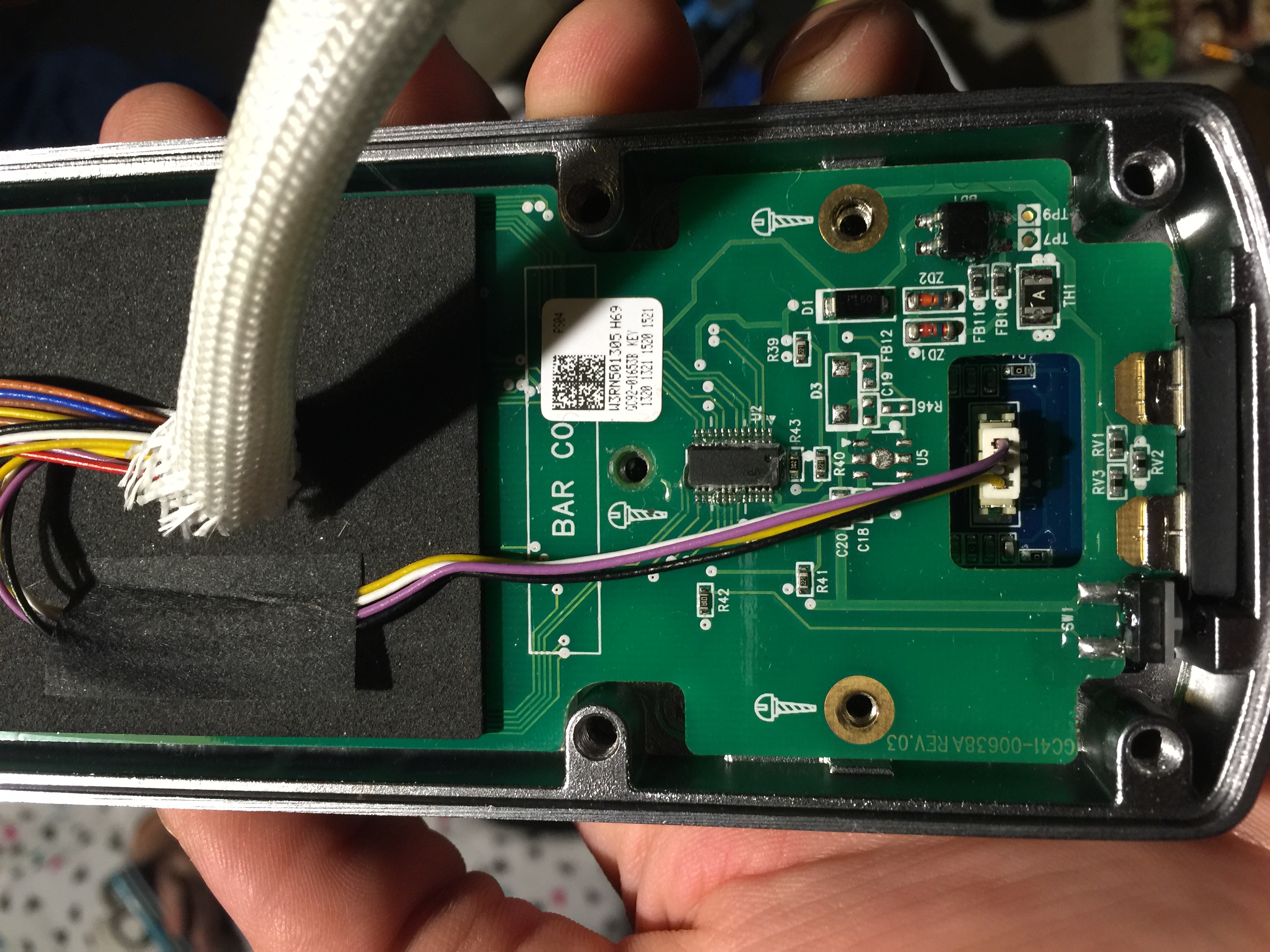
After taking the back off of the outdoor unit, I can see that the RFID board is completely separate from the main outdoor board, and connects directly to the indoor unit via 4 wires. Let’s get a better look at what’s under there.
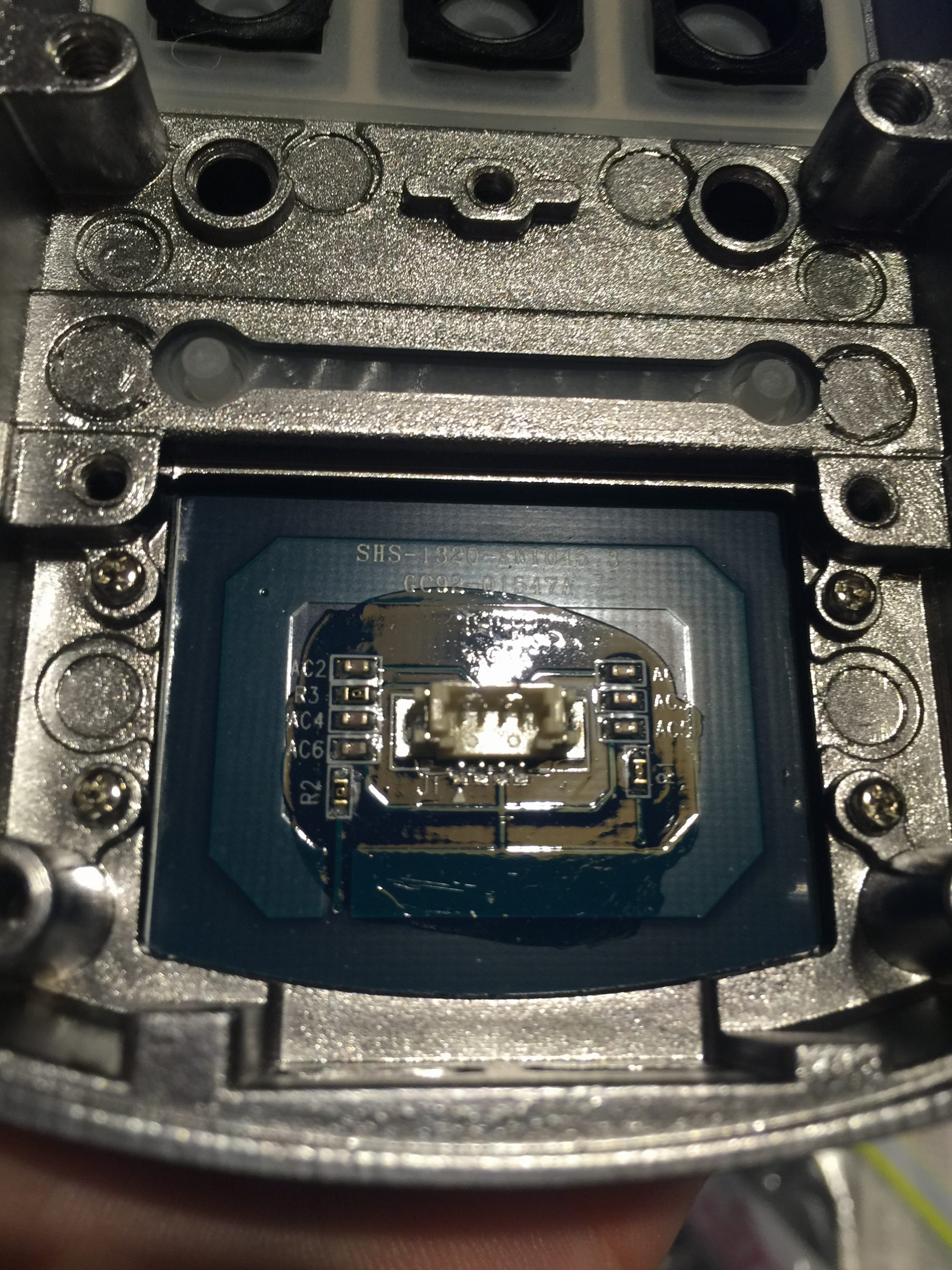
Ok this is interesting. Before starting this project I knew nothing about RFID circuits and antenna design, but the following diagram shows a basic RFID implementation, which bears a striking resemblance.
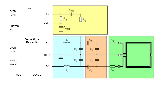
But there are a few components at play here – so we need to figure out at which point in the circuit is the separation between indoor and outdoor.
The Indoor Unit
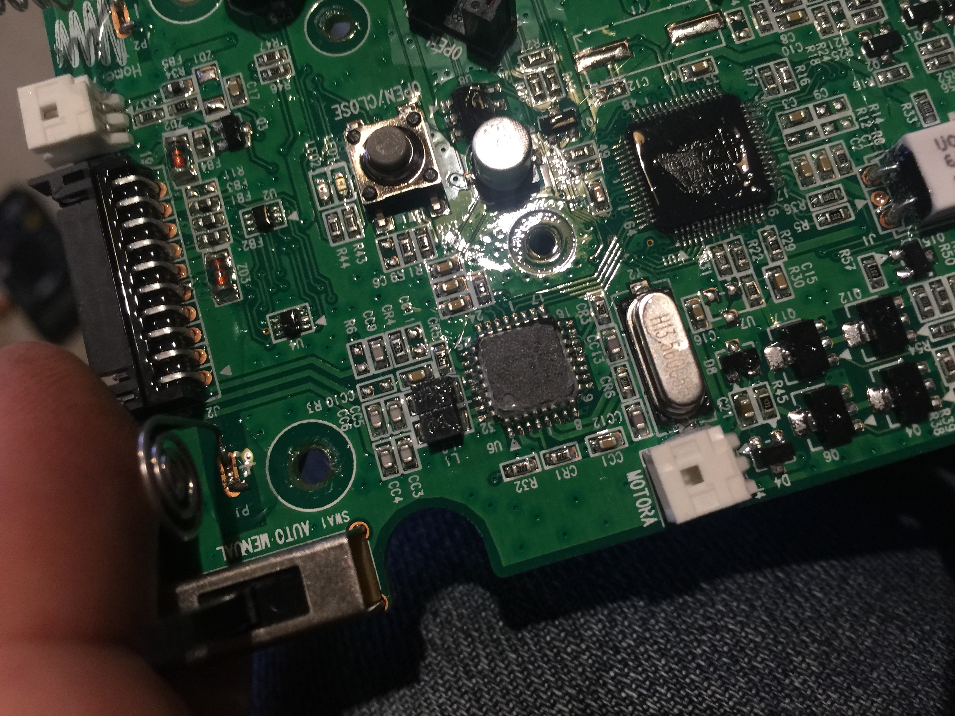
The entire circuit board was covered with a resin which makes it a little difficult to probe (and to photograph). It was also preventing me from seeing the markings on the chip to identify it. I removed the resin with my trusty pocket knife, but the text on the chip still eludes me. Nevertheless, you can see the inductors L1 and L2 which, means that logically these lines must connect to the antenna coil. It seems to be a straight path out of the inductors to the connector. The capacitors connect these lines to TGND, which also goes to the connector. 3 out of 4 wires are now identified!
All of these three wires are related to transmission, so it stands to reason that the 4th wire is the RX line, but which components are on which side of the wire?
Following the circuit on the indoor unit back from the connector, the signal goes through RC pair CC9/CR4, arriving at the RX pin on the IC.
With all that information in hand, it’s time to connect the antenna PCB to a new controller!
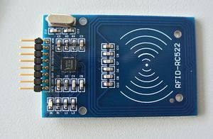
I selected the RC522 module because it’s cheap, and because the antenna circuitry is separated from the chip circuit (just like our lock). My original intention was to cut the board down so that the antenna was totally removed, but after some thought and a good hard look at the board layout, I realised that the pads where the tuning capacitors are would make an excellent place to solder my 4 wires.
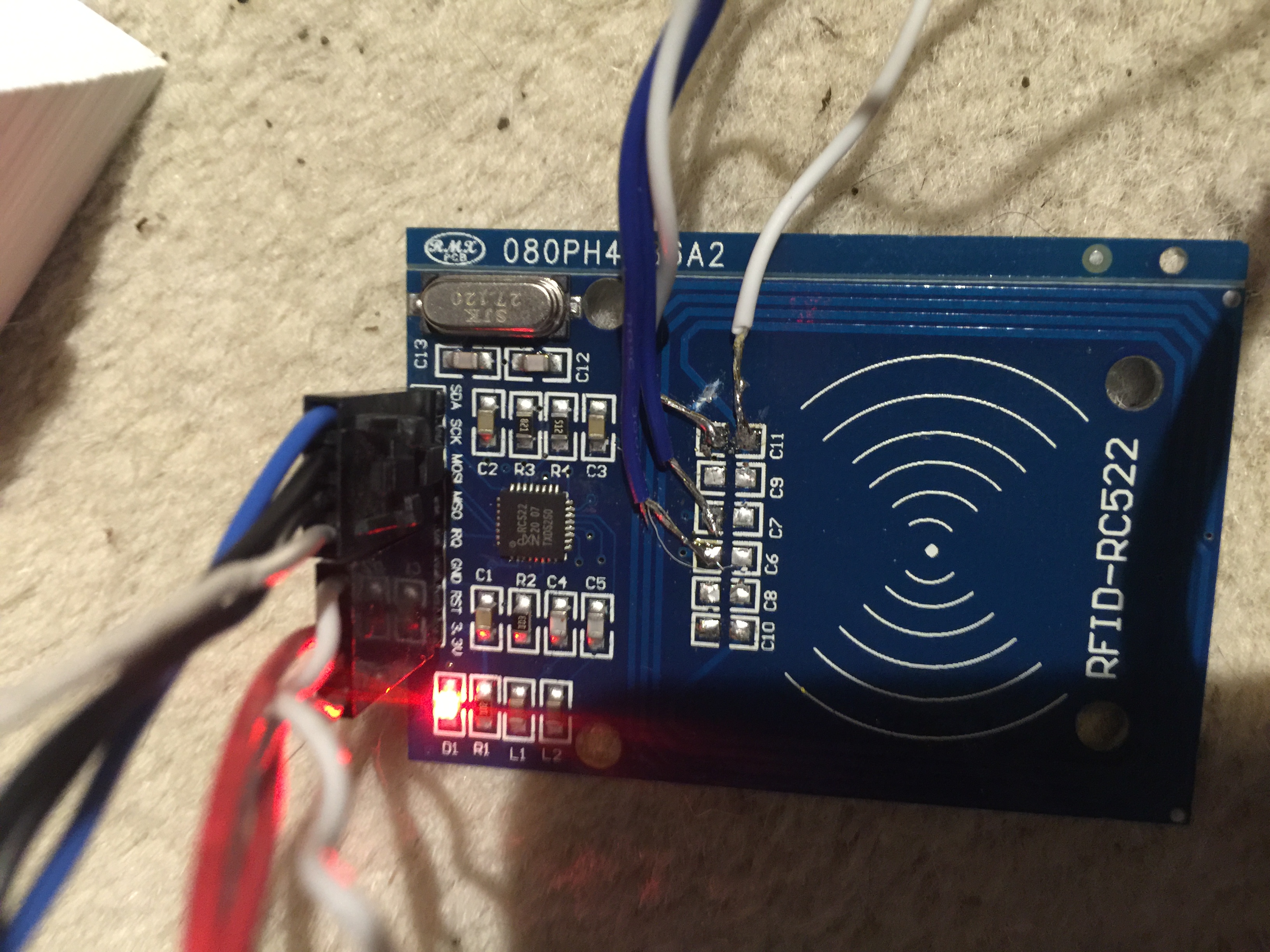
For testing, I soldered two wires onto the chip side of the pads which formerly held capacitors C6 and C7. These pads are connected on the underside of the board to the outputs of L1 and L2. I also soldered the TGND line to the chip side of C11 and RX to the other side of C11. Oh and I had to cut the traces to the onboard antenna.
Testing
Connecting the RC522 board up to the Raspberry Pi SPI bus I was able to read and write MiFare cards using the unmodified antenna built into the front of the outdoor unit!
An excellent python library for reading/writing MiFare cards using the RC522 can be found at https://github.com/ondryaso/pi-rc522. I will be building my software around this library 🙂
Conclusion
The Samsung SHS-1321, while very stylish and cheap was not quite what I wanted from an electronic lock, but with the addition of a Raspberry Pi, a cheap RFID controller and some patience, it is looking like I can have a managed Building Access Control system for very little cost.
I will be posting some code to drive this thing in the next post.
One thought on “Building a smarter door lock – Part 1: Hardware”
Hi
I really enjoyed reading this article!
I have a similar door lock, and was wondering if I could get it to work with the iPhone, particularly the “express transit card” setting.
I would love to see part 2, or pick your brain on how you programmed the controller.
Tim